The Hardware is completely based on open source modules like Arduino and Raspberry Pi. The signal conditioning shield is my own work but also available under MIT license.
Used Components
The hardware selection was based on the main requirements of the project:
- All Hardware modules should be open source and widely available around the world
- Signal Processing in Python, this requires the availability of the waveform data in the edge computer
- High Sampling Rates and ADC resolution >= 12 Bit
- Differential ADC Input
Arduino DUE
The Arduino DUE is a bit larger than the common Arduino Boards, but is the only one which can meet all the requirements.
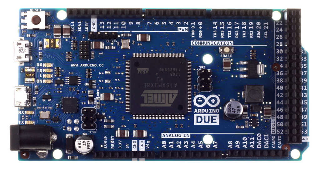
What makes the DUE so interesting?
- 12 ADC Inputs Single-Ended or 6 ADC Inputs Differential
- 12 Bit ADC Resolution
- DMA Data Transfer for gap-less acquisition
- USB Output which is capable for transferring data with 4.6 MBit/s in Serial-Mode
PQopen Shield
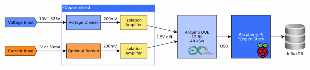
Back to the Start – we need measurement inputs which are capable of acquire the mains voltage as well as the current for power and energy monitoring. See more in the next chapter.
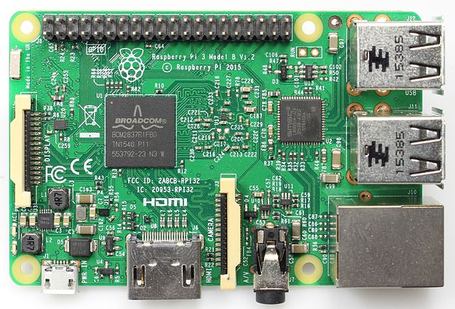
Raspberry Pi
This is the heart and brain of the resulting measurement device. It manages the signal processing, data storage and communicates with the network to post the data into a database.
Example Configuration
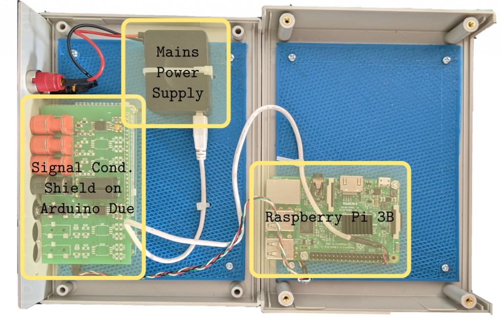
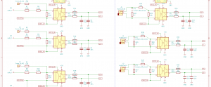
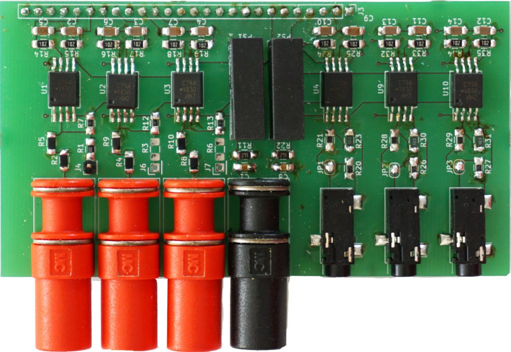
Signal Conditioning Shield
The Signal Conditioning Shield is designed to convert the relatively high voltage from the power grid and the signals from the current transducers to apply them to the Arduino DUEs ADCs. This is not all, the inputs are also insulated against the secondary side (Arduino).